Fm Modulator Circuit Diagram

Circuit diagram of fm generation.
Fm modulator circuit diagram. The 5000 ω potentiometer is used to bias the varactors for the best linearity. Fm receiver circuit diagram. The entire circuit diagram and the image of the circuit wired in the bread board is shown in the following figure. The carrier frequency is obtained by modulating the audio signals.
Circuit of fm generation on breadboard. The 555 modulator circuit is connected with the previous positive clamper circuit through a 1uf polarized capacitor. The frequency modulation fm signal is obtained by differentiating the carrier frequency and by allowing the audio frequency. Stereo fm transmitter using ba1404 ic this is a stereo fm transmitter circuit using an ic from rohmm semiconductors named ba1404 which is a monolithic ic and has a built in stereo modulator fm modulator rf amplifier circuitries.
The fm modulator circuit frequency modulation is built with a motorola mc1648p oscillator. New functions include frequency to wavelength conversion voltage divider circuit analysis ohm s law circuit analysis and more. The transistor is used for oscillator purpose in order to obtain radio frequency signal. Circuit diagram of 555 modulator.
I got the idea for this circuit from one of my professors. The signal strength of audio inputs into the transmitter is usually low therefore an amplifier is usually built to bring the signal level up. July 27 2020 new and improved mini circuits microwave calculator app the latest version of mini circuits microwave calculator app now includes 31 rf microwave calculations commonly used by engineers in the lab and in the field. 500hz so i built this by modifying the carrier and signal frequencies using only the.
You should be able to change the capacitance of the variable capacitor from a couple of picofarads to about 20 pf. The circuit diagram of the 555 modulator is given in the following diagram. Two varactors motorola mv 209 are used to frequency modulate the oscillator. Block diagram of fm transmitter working of fm transmitter circuit.
Frequency modulation is widely used for fm radio broadcasting. Let us consider the microphone to understand the sound signals and inside the mic. The only difference in this modulator circuit is that the pin number 5 is not connected to the positive via a capacitor but it is used to receive the modulating signal. It is also used in telemetry radar seismic prospecting.
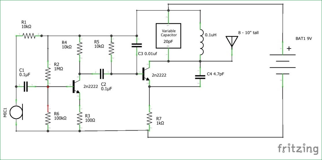
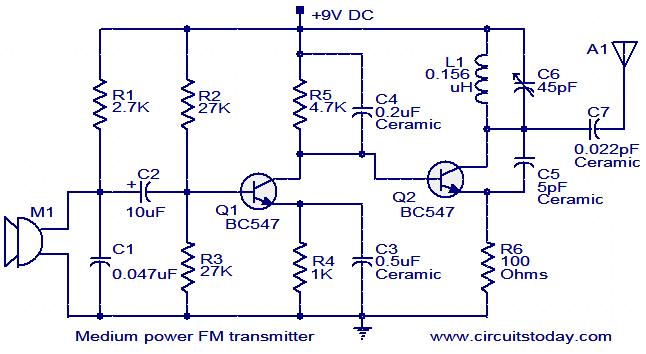
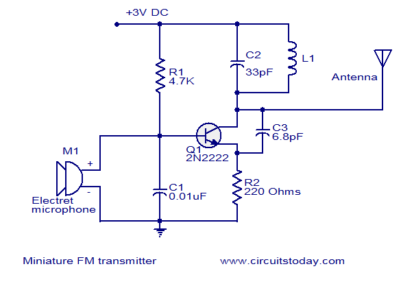
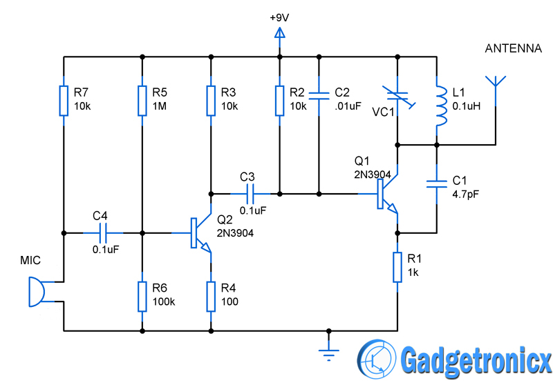
That design wasn t meant for passing frequencies high enough to be able to pass an audio file e g. The following circuit diagram shows the fm transmitter circuit and the required electrical and electronic components for this circuit is the power supply of 9v resistor capacitor trimmer capacitor inductor mic transmitter and antenna. This fm modulator can be operated between 76 to 108mhz. Typical fm transmitter design s usually follow the block diagram below.


